Automating Waste Management: PLC-Based Automatic Drainage Water Monitoring & Control Systems
Introduction
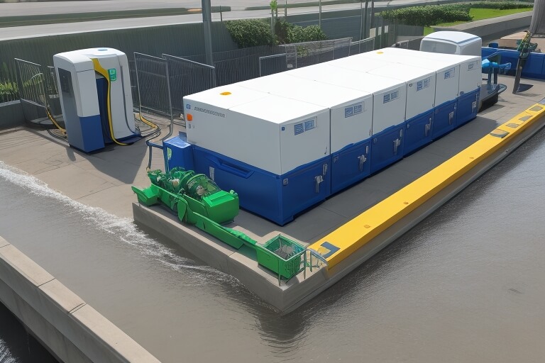
Addressing safety and efficiency concerns in waste management, our PLC-Based Automatic Drainage Water Monitoring & Control System offers a technologically advanced solution to manual drainage cleaning. This innovation reduces human interaction with hazardous environments while elevating the effectiveness of waste disposal.

Technical Components
The backbone of this automatic drainage system consists of multiple high-end components:
- PLC (Programmable Logic Controller): The brain of the system, responsible for coordinating all actions.
- Gas Sensor: Detects and distinguishes between toxic and non-toxic gases.
- Pressure Sensor & Level Sensor: Monitors water levels and internal pressure within the drainage pipes.
- Solenoid Valve & Gas Exhauster: Responsible for the filtration and treatment of waste gases.
- LED Lamps, Buzzer, and Push Buttons: Provide visual and auditory alerts.
- DC Motor & Relay: Powers the system and manages the electrical circuitry.
Functionality
The system operates in a supervisory control mode with real-time data acquisition. When the level sensor detects high water levels or the gas sensor picks up harmful gases, the PLC activates the necessary safety mechanisms. This may include opening the pressure valve, initiating the gas exhauster, or activating the water pump, among other actions.
Applications
This system is particularly beneficial in environments that require stringent waste management protocols, such as industries and hospitals.
Safety Measures
Built with safety as a priority, the system’s gas and level sensors, along with other components, ensure that toxic substances are handled carefully, mitigating risks associated with manual drainage cleaning.
Conclusion
The PLC-Based Automatic Drainage Water Monitoring & Control System stands as a leap forward in achieving safe and efficient waste management. Its advanced components and robust functionality make it a must-have in modern waste management solutions.
Sample Code
The example assumes:
- ‘
I0.0‘: Level sensor input - ‘
I0.1‘: Gas sensor input - ‘
Q0.0‘: Water pump output - ‘
Q0.1‘: Gas exhauster output - ‘
M0.0‘: A memory bit to hold an intermediate state
Network 1 : Check Level Sensor
I0.0 ------|( )|--------------+( )--------(S)--------M0.0


Network 2 : Check Gas Sensor
I0.1 ------|( )|--------------+( )--------(S)--------M0.0


Network 3 : Activate Water Pump if Level is High
M0.0 ------|( )|-----------------------------------( )---------Q0.0


Network 4 : Activate Gas Exhauster if Gas Detected
M0.0 ------|( )|-----------------------------------( )---------Q0.1
In order to download the PDF, You must follow on Youtube. Once done, Click on Submit
Follow On YoutubeSubscribed? Click on Confirm
Download Automating Waste Management: PLC-Based Automatic Drainage Water Monitoring & Control Systems PDF


