Solar Efficiency with Sun Tracking Solar Panel Using Arduino
Introduction
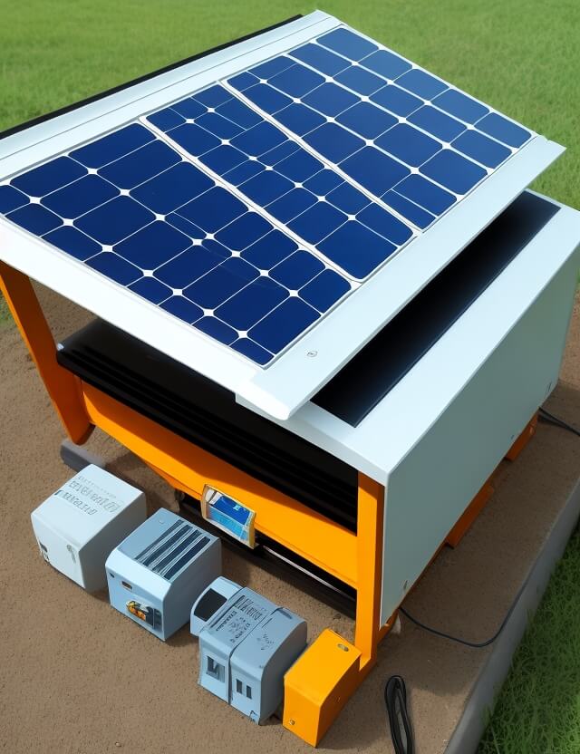
Solar energy has emerged as an inexhaustible resource for a more sustainable future. To harness this energy more efficiently, sun-tracking solar panels using Arduino offer a significant technological leap. By focusing the panel to track the sun’s movement across the sky, these systems increase the amount of solar energy that can be converted into electricity.

Why Sun Tracking?
Conventional solar panels remain fixed in one position, capturing only a fraction of available solar energy. With a sun tracking system, you can ensure that the solar panel is always aligned to the sun’s position, maximizing efficiency and power output.
Core Components and Hardware Specifications
- Solar Panel: The primary source for capturing solar energy.
- Arduino Controller Board: Acts as the brain of the system.
- Motor: Facilitates the mechanical movement of the solar panel.
Software Specifications
- Arduino Compiler: For programming the Arduino board.
- Programming Language: C
Working Mechanism
The Arduino controller board is connected to the motor and the solar panel. The system scans from one horizon to the other, identifying the position of maximum solar energy. Based on the data, the Arduino board signals the motor to adjust the panel’s orientation accordingly.
Block Diagram of Solar Tracking System Using Arduino
The block diagram serves as the project’s backbone, offering a visual representation of the hardware and software interconnections.
How to Implement
- Initial Setup: Connect the solar panel, Arduino board, and the motor.
- Programming: Use the Arduino compiler and C language to program your Arduino.
- Testing: Ensure the system effectively tracks the sun and positions the panel for maximum energy capture.
Future Prospects
The scalability and effectiveness of this system offer a promising avenue for larger applications, including industrial and agricultural settings.
Sample Code
#include <Servo.h>

// Define servo motors
Servo horizontalServo;
Servo verticalServo;

// Define light sensors (LDRs)
int LDR1 = A0;
int LDR2 = A1;
int LDR3 = A2;
int LDR4 = A3;

void setup() {
  // Initialize servo motors
  horizontalServo.attach(9);
  verticalServo.attach(10);
}

void loop() {
  // Read LDR values
  int LDR1Reading = analogRead(LDR1);
  int LDR2Reading = analogRead(LDR2);
  int LDR3Reading = analogRead(LDR3);
  int LDR4Reading = analogRead(LDR4);

  // Calculate average readings for horizontal and vertical axis
  int avgHorizontal = (LDR1Reading + LDR2Reading) / 2;
  int avgVertical = (LDR3Reading + LDR4Reading) / 2;

  // Determine the servo position based on LDR readings
  int horizontalPosition = map(avgHorizontal, 0, 1023, 0, 180);
  int verticalPosition = map(avgVertical, 0, 1023, 0, 180);

  // Move the servo motors to the new position
  horizontalServo.write(horizontalPosition);
  verticalServo.write(verticalPosition);

  // Wait before taking the next reading
  delay(1000);
}
In order to download the PDF, You must follow on Youtube. Once done, Click on Submit
Subscribed? Click on Confirm
Download Solar Efficiency with Sun Tracking Solar Panel Using Arduino PDF


